3BITSWITCH
This module gives you a 2 to 8-channel switch, controllable from the buttons on the front panel or via the gate inputs. The circuit can be used bidirectionally; i.e a signal can be sent to one of eight destinations or one of eight signals can be selected to go to the output. Its a variation of the 3VCSWITCH. It uses a 4051 chip, a 1-to-8 multiplexer/demultiplexer.
Interesting patterns can be generated by patching LFOs or triggers to the GATE inputs. It pairs wonderfully with trigger modules.
The state of the bits A, B and C determines the INPUT/OUTPUT. For example, let's suppose we have a signal coming into IO1:
- If all bits are LOW (0V), the signal will go through OUTPUT 1
- If A is HIGH and both B and C are LOW, the signal will go through OUTPUT 2
- If B is HIGH and both A and C are LOW, the signal will go through OUTPUT 3
- ... and so on.
A, B and C set the binary number of the INPUT/OUTPUT.
| A | B | C | Output |
| 0 | 0 | 0 | 1 |
| 1 | 0 | 0 | 2 |
| 0 | 1 | 0 | 3 |
| 1 | 1 | 0 | 4 |
| 0 | 0 | 1 | 5 |
| 1 | 0 | 1 | 6 |
| 0 | 1 | 1 | 7 |
| 1 | 1 | 1 | 8 |
A nice extension for this module would be converting it to a variable sequencer, adding a pot for each channel then routing their signal to a single OUTPUT.
Inputs
- IO1 - IN/OUT going to/from OUTPUTS
- GATE1 - a +5V signal here sets bit A to HIGH
- GATE2 - a +5V signal here sets bit B to HIGH
- GATE3 - a +5V signal here sets bit C to HIGH
- +5V - output giving +5V
Outputs
- 1-8 - OUT/IN from/to IO1
Controls
- A button - When pressed sets bit A to HIGH, ignoring the GATE1 signal.
- B button - When pressed sets bit B to HIGH, ignoring the GATE2 signal.
- C button - When pressed sets bit C to HIGH, ignoring the GATE3 signal.
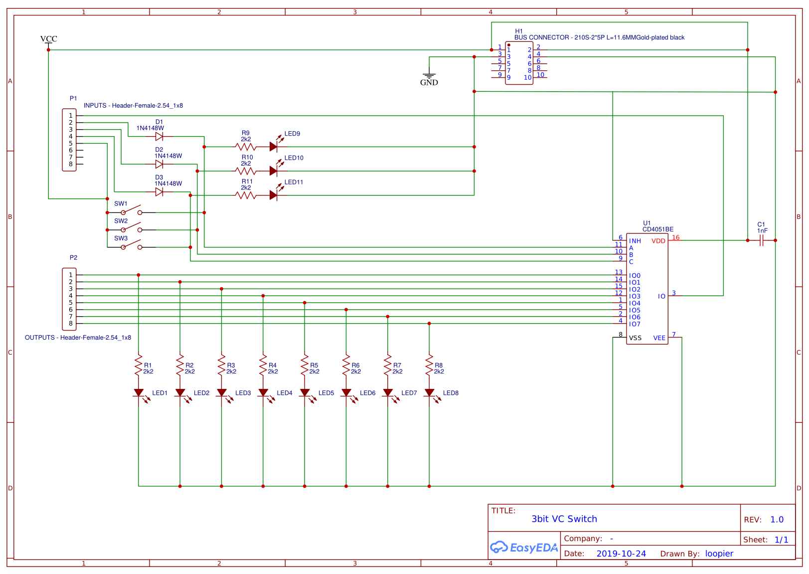
Schematics
Patch Suggestions
This module is excellent for providing variation in rhythms / sequences by cutting a trigger in or out via the buttons if "playing" the AE modular, or the gate inputs - the latter can be done with an LFO, envelope or one of the sequencer modules. It works really well with all of the sequencer and counter/divider modules. Combine them to get even more interesting results.
To use it as a gate/trigger sequencer, patch the +5V output to the IO1, then any combination of LFOs and/or other triggers to the GATEs. Different patterns will be sent through the OUTPUTS.
Following is a video featuring the module:
+5V patched to IO1
Each of the OUTPUTS is patched to one of the DRUMKIT010 inputs.
Two MM-DIV outputs are patched to GATE1 and GATE2 to provide steady rhythm.
GATE3 receives the signal from ALGODRONE's output, giving the whole thing a touch of chaotic randomness.
The DRUMKIT is then sent out after some minor processing.
<-- Back to the Advanced DIY Index
This manual is a community work in progress. If you would like to help out with completing this manual please send a PM to @admin at the AE Modular Forum. You can find the status of each page on the Trello board at https://trello.com/b/HNd0dBt7/ae-manuals