Signals on the Bus Cable
All modules are connected with a 10-pin ribbon cable that runs below the modules. Each module is plugged onto this bus cable with a 10-pin connector.
A master module is usually the source for this ribbon, supplying both power and control signals (derived from midi).
The master module has 2 connectors for 2 separate ribbons.
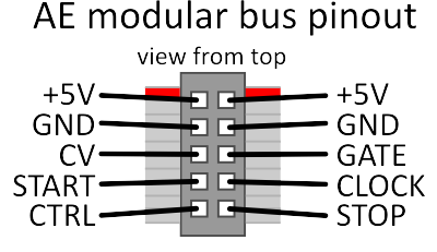 |
The top 4 pins are used for power. The remaining 6 pins are all derived from MIDI by the master module.
| PIN | | | PIN | ||
|---|---|---|---|---|
| supply voltage; red stripe on the ribbon cable | +5V | | | +5V | supply voltage; red stripe on the ribbon cable |
| ground signal | GND | | | GND | ground signal |
| pitch CV 1V/oct (label: BUS CV) | CV | | | GATE | gate (0 or 5V) (label: BUS GATE) |
| start of clock used for reset (label: B.START) | START | | | CLOCK | clock pulse (24ppqn?) (label: B.CLOCK) |
| CC #20 (label: BUS CTRL) | CTRL | | | STOP | stop clock signal (label: B.STOP) |
NOTE: the control signals should be considered as output only, since they are pushed by the master module.
NOTE: All modules use the same 5V / Ground rail so modules need to take care not to induce a ripple voltage which can introduce noise.
How to make your own ribbon cable
You can of course make your own, it's really nothing special. Here is a general guide on how to make those: https://startingelectronics.org/articles/IDC-ribbon-cable/