Project 01 - CD40106 Square Wave Oscillator
This tutorial will be about how to build a very simple oscillator with your BRAEDBOARD and the parts that come with it.
To give you an idea here is a little demo-recording using the breadboard-patch to be explained below along with a little rhythm from KICK and a bit of echo and reverb from DELAY and MULITFX.
https://soundcloud.com/taitekatto/braedboard-cd40106
If you are not familiar with using breadboards at all, we suggest you could have a brief look on the net what it is about, for instance using the links as below.
The important thing about breadboards in general is the fact, that vertical columns are connected, unless there is a kind of horizontal deepening between them, whereas lines are not connected.
As a speciality with BRAEDBOARD, the upper (red) breadboard has a column of +5V on the leftmost column and the lower (black) breadboard has a column of ground on the leftmost column. This is a kind of substitute for the additional power-rails (“bus strips”) you may have seen in the video or Wikipedia-entry mentioned above.
The basic component of our project here is an integrated circuit called CD40106 which among other things can be used to easily build up to six square wave oscillators.
You’ll find many information about this IC on the net, here are some very good explanations by Pete Edwards / Caspar Electronics for instance:
But we will not bore you with technical details about all this, but instead explain how to build a one-oscillator circuit with variable pitch very simply from scratch.
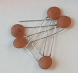
In addition to the IC we will use a capacitor, one of the two potentiometers and several patching wires. The capacitor to be used looks like one of these and should be marked “104”.
This is the schematics we will use, side by side with how it should look on your system:
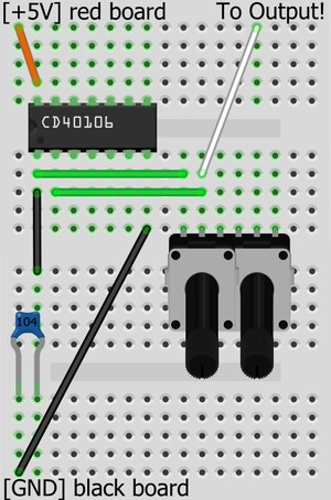 | 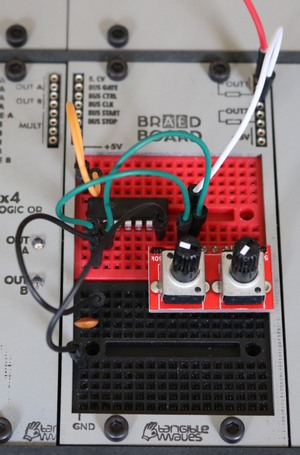 |
Put the CD40106 on the upper, red breadboard of BRAEDBOARD. The half-circle shaped notch must be at the left hand side!
Put the chip one column from the left. (You should only put components all way left to ground or power them!) To prevent a short-circuit, make sure that the IC is situated above this deepening.
- Connect the leftmost pin on the upper side of the IC with +5V as shown above. (orange cable)
- Connect the rightmost pin of the IC on the lower side with Ground, as shown above. (black cable)
- Put one of the little brown ‘104’ ceramic-capacitors as pictured above, so that it connects to Ground with one ‘leg’ and to the leftmost pin of the IC with the other ‘leg’ using the black cable as pictured above.
- Connect the left potentiometer with the first and second pin of the IC as pictured, so that the first pin of the potentiometer connects to the lower, leftmost pin of the IC and the second pin of the potentiometer connects to the second pin from the left of the lower pins of the CD40106. (green cables)
- Connect the output as pictured using the white patch cable (“jumper wire”) above. This connects the second pin on the bottom row of the IC as well as the second pin of the potentiometer with the ouput-resistor of the BRAEDBOARD. (Third jack from the top on the right hand side as pictured below)
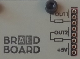
Connect “OUT1” with whatever you find appropriate on the AE Modular, for instance using MIXER 4-4.
Now you can change the pitch of your square-wave oscillator by twisting the left potentiometer.
Have fun!
After you've had enough of a play with this circuit, just leave everything patched and go to Project 2 - Frequency Modulation with the CD40106 which is an easy and interesting enhancement of this build.
<-- Back to Easy Projects for the BRAEDBOARD Module