Physical characteristics
- Ribbon Cable
- Module Dimensions
- PCB - Control Elements and Placement
- Front Panels
- Case
- Module Mounting
Ribbon cable
A standard 10 pin ribbon cable is used, and folded, and has 16 connectors on it.
The Type B cable has a longer distance to connect the master module, since it needs to go to the bottom row, so is an additional 100mm.
Module
Module Dimensions
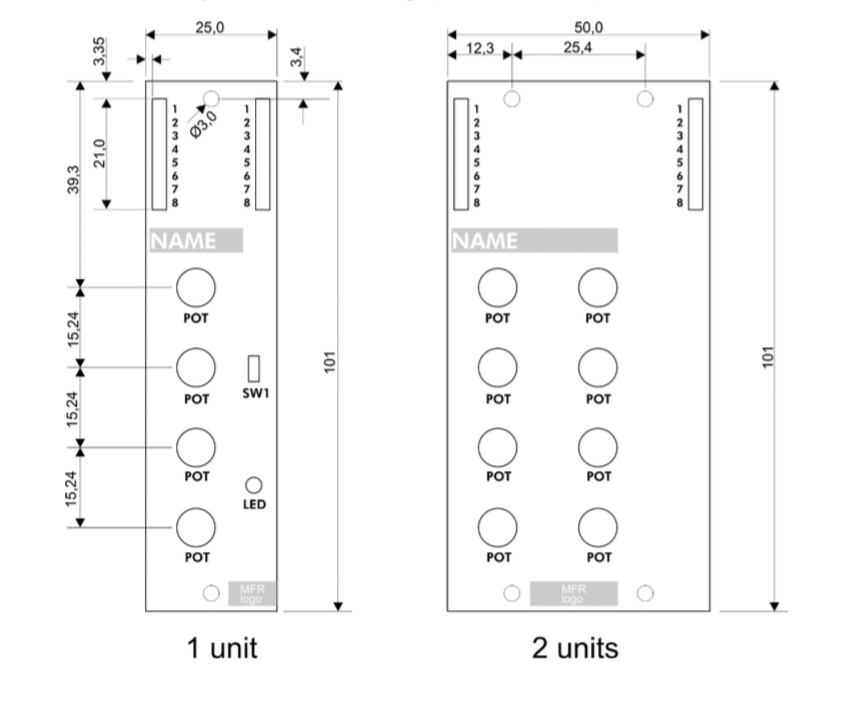
Size of the modules (single unit) is 101mm h x 25mm w. Wider modules are a multiple of 25.4mm (1”) minuses approx. 0.5mm gap tolerance
PCB (single unit) is 100 x 25mm
The standards case allows for a depth of 25mm, plus a 1.5 mm faceplate.
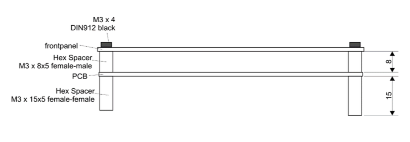
A module is composed of
- The front panel (thickness : 1.5mm)
- Hex spacers M3 8mm high (female-male) between the front panel and PCB
- PCB (thickness: 2mm)
- Hex spacers M3 15mm high (female-female)
The modules are mounted in a case/rack with M3 screws from the bottom (through the bottom plate).
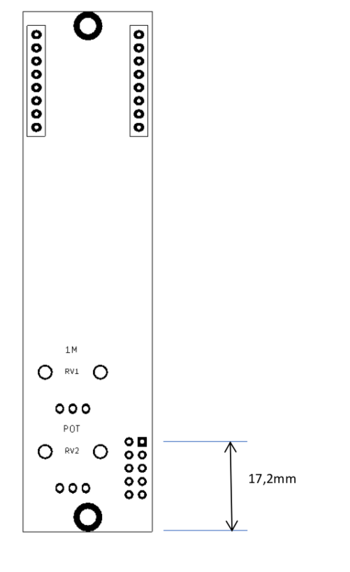
PCB - Control Elements and Placement
On the top end of the module, there are two female pin headers (usually 8p.); left the module inputs, right the outputs.
The pin headers are 2,54mm grid (the usual Arduino type headers)
Potentiometers are RK09 type, 20mm high. Typically no additional knobs, only the pot axis.
For connecting to the bus cable, each module has a 2x5 male pin header at the right bottom end of the module
Front Panels
- Material: 1.5mm MDF board, primed and sprayed with color, could be also Acrylic or aluminum...
- Marking/printing: is made originally by a rubber stamp and special stamp color; any other options are possible of course.
- Mounting: front panels are mounted with M3x4 screws, black, DIN912 cap screw with an inner hex
Ribbon connector example: https://uk.farnell.com/molex/10-89-7102/header-board-to-board-2row-10way/dp/2293829
Headers example: https://uk.farnell.com/multicomp/2212s-08sg-85/socket-pcb-1-row-8way/dp/1593463 e(these are a little bit short though)
NOTE: trimpots are placed on the underside of the module, with holes in the case base to allow for adjustment.
Case
The standard case has an internal dimension of 406.4mm for 16 U. There are currently two variants: one- or two-row. The two-row has a ‘wall’ between the top and bottom row, this provided extra stability. This ‘wall’ has an opening to allow for the lower ribbon cable (type B) to pass from the master module to the lower modules.
To allow for mounting, each row of the case has a series of holes 25.4mm apart for the top and bottom of the module. Additionally, at the left-hand side of the case, there are additional holes in the bottom that align with the tuning trimpots of the 2OSC and VCO modules.
Finally, a hole is situated at the top of the left hand ‘end cheek’ of the case to allow for the DC jack of the master module.
NOTE: From the ‘holes’ in the case, you can see there is a notional position for the master module and some oscillators modules.
Module Mounting
The modules are standing on metal PCB standoffs , as can be seen here:
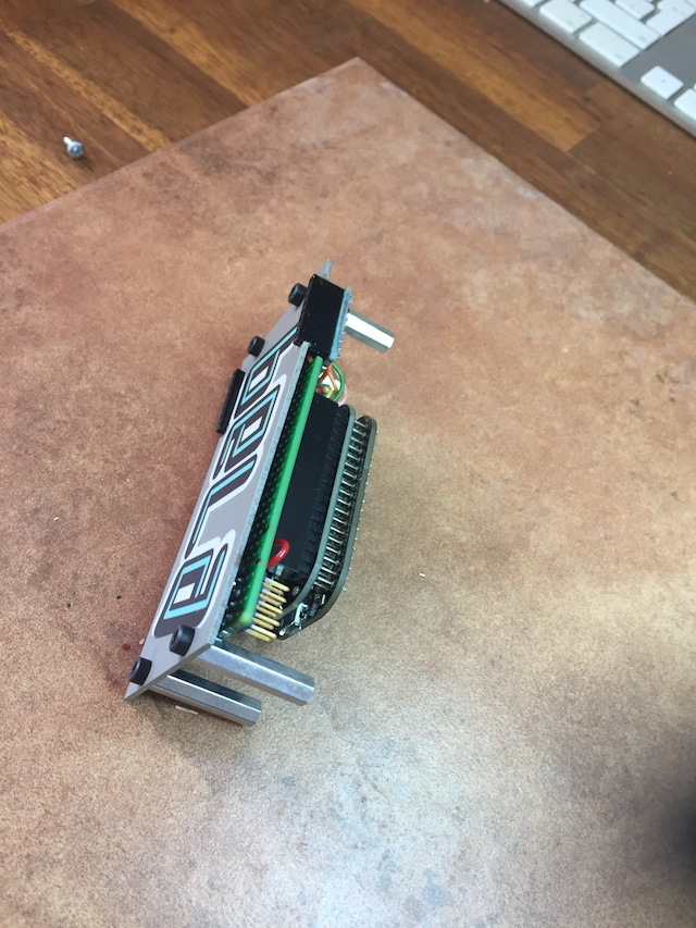
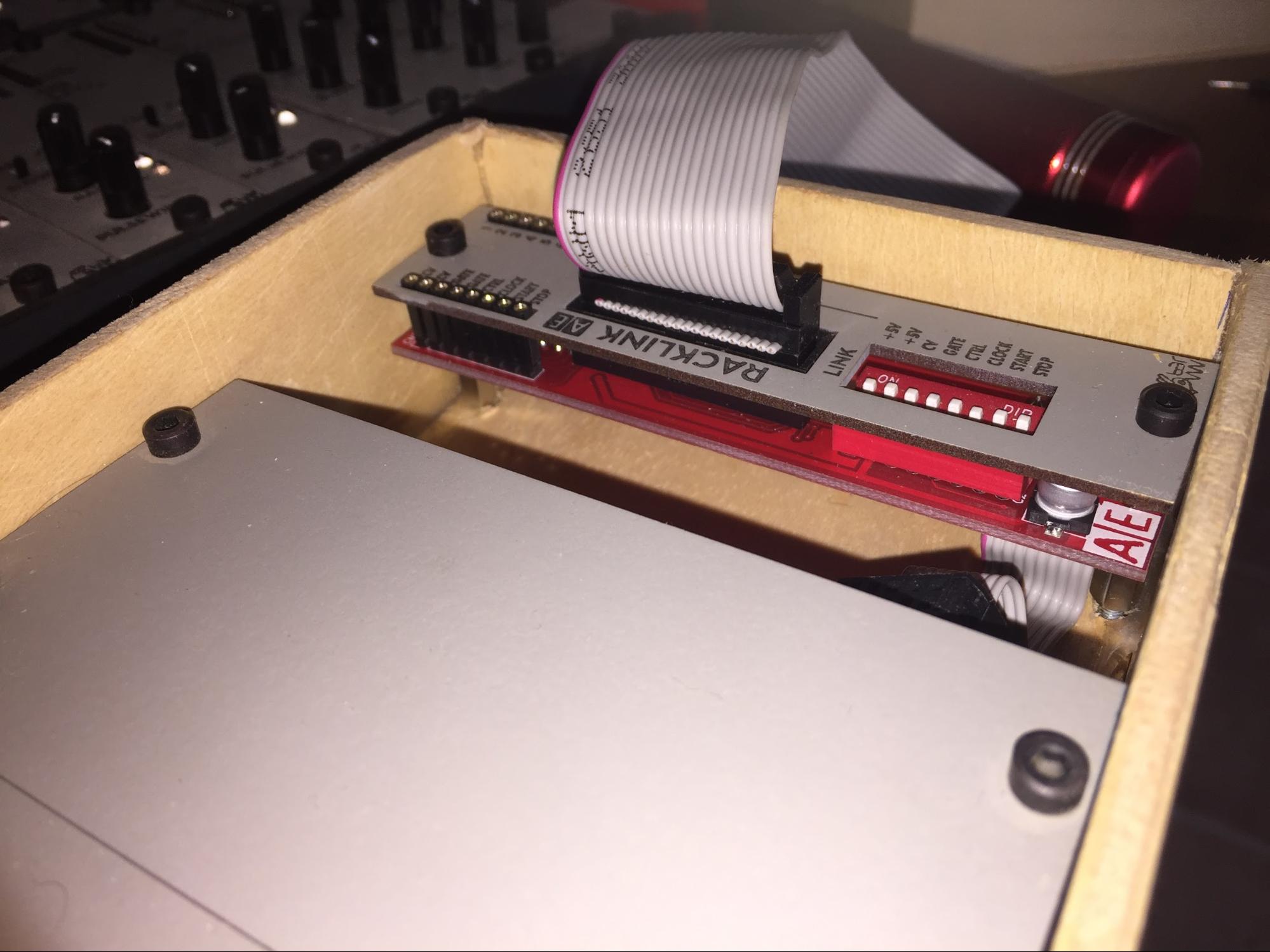
The module is secured then by screws which goes through the case bottom. Therefore, it should be noted that some of the ‘stability’, esp for 1U modules, is provided by other modules sitting next to them and the case perimeter. (less so with 2+ Units, since they use 4 posts)