Considerations for DIY modules
Here are some considerations for creating DIY modules.
Power
Power is shared across modules, it’s imperative you keep it ‘clean’ and free of ripples otherwise you will induce noise onto other modules.
Generally it's a good idea to add a 100nF (approx.) capacitor near digital chips from +5V to ground; this has the effect to smooth the power supply from sudden minor changes caused by momentary higher consumption of ICs, microcontrollers.
Things with heavier voltage swings you may need an inductor, some discussion of this can be found here.
(also for microcontrollers with higher current requirements, keep an eye on total used - bare in mind most AE modules are using very little current)
Inlets
In AE, digital inputs are pulled to ground by a 100k resistor; this is enough to tell the chip input "low" and high enough to not affect a "real" input signal.
Module Depth
Since the depth is limited to 25mm, it’s quite limited in space. Remember you will have to have space for the front panel components (that live beneath the faceplace) and also space underneath for the ribbon connector.
Faceplate
The easiest thing to use as a starting point is a blank panel, as it gives you the holes for mounting in the correct place.
The headers and drill points for mounting are very close to the edge on the factory modules.
Getting the faceplate at the same levels is a challenge. The general idea, as used by tangible waves is a sandwich
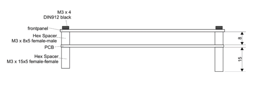
Faceplace ← gap (for components) ← pcb ← gap (for ribbon header) ← bottom of case.
Of course you can use variations of this, in particular you may find your PCB or faceplate material is thicker. The factory modules, allows for a 2mm thick pcb/ 1.5mm faceplate, but if you use 3mm then you will need to reduce the size to the lower hex spacer (aka standoff).